On most late-model cars, there are hundreds of messages with thousands of parameters being transferred between controllers, this leads to the idea that EVERYTHING is being able to be controlled by CAN BUS messages. This simply is not the case. If a controller doesn’t need to send internal data to another controller then it won’t. Simple as that.
So why am I writing this? Because the biggest waste of time in reverse-engineering the CAN BUS is looking for a command or a parameter that simply isn’t there. You need to have the notion that everything is not available and sometimes you won’t find it no matter how much you look.
So how do you determine how long to spend on looking for a parameter or command? Well the answer, I think, depends on the importance of getting the parameter. I take the example of trying to find Engine Speed on a CAN BUS. Engine Speed is nearly universally available on today’s CAN BUS vehicles. It is usually simple to find and scale, so not much time is wasted, but in contrast, Outside Air Temp may not be collected by a module on a car or may not be broadcast by the controller that collects the data. In the first instance where it is not collected there are ways to find this out before hand. You can look at publicly available wiring diagrams that show (or rather do not show) that there is no Outside Air Temp sensor on any controller. This will save you time and frustration.
In the case of commands sent over CAN BUS (i.e. Unlock from a key fob). These can be tested by capturing all of the messages while you pressed the unlock button, then play those messages back to the network one or two times to see if the doors unlock. Why does this work? If the message was sent over the CAN BUS then by playing all of the messages back on the bus you should have the same result as when you pressed the button such as any parking light flashing, horn honking, etc. If you do then you know the message is broadcast over the CAN BUS, if not then you can assume that it is most likely not available. If it is not available, simply move on. You can try the process again one or two more times, but you probably did it right the first time.
So good luck and as always let me know what you’re working on, I’m always interested to help.
Monday, May 24, 2010

Automotive Embedded Security
I found this today and thought I should share it.. Center for Automotive Embedded Security
Scanning for Diagnostic Data.
Because diagnostic data is built on top of a standard Transport Protocol (ISO 15765-2), you can use this knowledge to see which diagnostic service a particular vehicle supports and which parameters or sub-functions it may support.
Step 1. Finding Nodes’ Diagnostic IDs.
We must first have all of the nodes enumerated with Physical IDs and their respective response IDs (Note: sometimes there may be an ID that is a Functional ID. That means more than one node will respond to request sent on this ID). To do this I usually send the Tester Present Request (Service 0x3E) to each CAN BUS ID. If you are working with a 29bit system this may be daunting simply because of how many possible IDs there are; you may have to find a shortcut instead of request each ID. However on 11bit systems this is quite easy.
Start by sending tester present to ARB ID 0x001. This message would typically look like this:
0x001 01 3E 00 00 00 00 00 00 OR 0x001 02 3E 01 00 00 00 00 00. Try them both and see which works. Next simply increment your arbitration ID by one: 0x001, 0x002, 0x003, … 0x7FF. You will know that a node has diagnostics on it because you will see a response from the node after you send your request. You would typically see this: 0x7E8 01 7E 00 00 00 00 00 00. The 0x7E is the positive response to your 0x3E request (tester present). Write down (or log) the request ID AND the response ID and save them for later. Essentially the request ID is how you query the controller and the response ID is data you will get back from that specific controller. Keep in mind that you may get some CAN BUS errors. This is to be expected, but should not cause concern. You may also have some strange affects on the car such as a windshield wiper move or blinker kick in. This is because you are sending data on the bus that is interpreted by other controllers and you may have inadvertently activated another command. Cool, huh?
Step 2. Finding Supported Services.
This can be a bit tricky only because some services may require a certain message length (i.e. you may have to have 0x04 in the first data byte in order to get a positive response from the controller), but this is usually not the case. In order to do this you must remember that the service ID for a diagnostic command is found in the second byte (ARBID, B1, B2, B3, etc). So your first request might look like this: 0x7E0 01 01 00 00 00 00 00 00, where byte 2 contains the service. In this case we are not sending any protocol data. Diagnostic services are broken into ranges. This is because the request IDs and positive response IDs don’t over-lap, and since we are not interested sending the responses, we can remove the positive response IDs from the services we will request. Service request IDs are as follows: 0x01-0x3E, 0x80-0xBE. (0x3F is reserved, 0x7F is for negative responses and 0x40-0x7E and 0xC0-0xFE are reserved for positive responses coming back from the ECU).
Now that we know what our range is, we can simply send a request and based on its response we will know if this is a service that is supported. We send 0x7E0 01 01 00 00 00 00 00 00 and we get back 0x7E8 03 7F 01 12 00 00 00 00. The response is a negative response because there is a 0x7F in the second data byte. This tells us that there was a problem with our request, but does NOT mean that the service is not supported. We have to look at byte 4 to see why our request failed. In this case we got a 0x12 Negative Response Code (NRC). 0x12 means Sub-Function not supported (please see list below for other NRCs). So it’s telling that the service IS support but the sub-function (which we didn’t send one in this case) is not supported. In fact we can ignore all NRCs except 0x11 and 0x78. NRC 0x11 means that the Service is Not Supported. This gives us a definitive NO that we cannot use this service on this controller. NRC 0x78 doesn’t tell us anything, yet. In fact it means Response Pending. It may response later with another NRC or with a positive response. Other than a NRC 0x11, a simple No-Response will tell you that the controller does not support your service. Simply waiting around 100 milliseconds (ms) will be sufficient proof that the particular service is not supported on your controller.
Step 3. Finding Parameters.
This is the most dynamic of steps. It requires some understanding of the service that you are working with. For example, you may be using a service that has a sub-function or a service that has a parameter and this parameter may be 1 byte, two bytes, three, etc. So you will have to prepare yourself for a lot of negative responses (I hope you don’t fear rejection).
So here is what we do now, send our request but increment the bytes,
0x7E0 02 01 00 00 00 00 00 00,
0x7E0 02 01 01 00 00 00 00 00,
0x7E0 02 01 02 00 00 00 00 00, etc..
If you are getting positive responses back from the controller, then you have won. However if the controller is sending back negative responses then you’ll have to adapt. For instance you may get a NRC 0x22, this means “Conditions Not Correct, Sequence Error”. This NRC is particularly vague. It typically means that you must send a Start Diagnostic command first or that the key must be in the ignition, or that Venus and Mars must be in alignments. So you will just have to work with what you have. But if you get a NRC 0x12, you will know right away that this sub-function or this parameter ID is not supported by this controller and you can move on to the next one.
As you can see the trick is to automate this process. To write each message and handle each repsonse can be difficult.
| NRC | Long Name |
| $11 | Service Not Supported |
| $12 | Sub Function Not Supported - Invalid Format |
| $22 | Conditions Not Correct Or Request Sequence Error |
| $31 | Request Out Of Range |
| $35 | Invalid Key |
| $36 | Exceed Number Of Attempts |
| $37 | Required Time Delay Not Expired |
| $78 | Request Correctly Received-Response Pending |
Saturday, May 15, 2010
Hanging Guy For Halloween
I needed a thrashing body that's suspended overhead for my haunt. Not hanged, but a "captured" person, hanging from the back by a rope under its arms and over its chest. I built it out of PVC pipe (of course) and used a small air cylinder to make it thrash as if trying to get out of its bonds. It works quite well. the finished body only weighs 5 pounds (mostly clothes) and is quite sturdy. I've just finished the body, so the description that follows may lack some needed detail. But, feel free to experiment! There is no ONE right way to build anything for Halloween. And if it works, but it ain't perfect, say what we do:
|
| The body is constructed from different sizes of PVC pipe. The pipe thickness is "Schedule 40" or thicker. Just pick the 'thick pipe' at the store. PVC comes in 10' lengths, so you will need one 10' piece of 1", 3/4", and 1/2" pipe. And you'll have some left over. You'll need these PVC fittings:
Also you'll need:
Construction of the body is straight forward, cutting the pipe and assembling it with the fittings. I'd recommend cutting all the pieces and test fitting them together first to be sure everything goes together BEFORE you glue it together. Once glued, it does not come apart! Hint: When building a new prop, I test fit everything. Then when it all looks right, I drill small holes into the fittings and through the pipe, then insert a screw to hold it together. This gives lots of flexibility just in case something needs to be taken apart again. I have several props that only have screws holding them together and have worked well for several years. |
| ||||||||||||||||||||||
| The hip joint is built by using a single piece of 3/4" pipe that goes through the 1" tee fitting and connects to each leg. Add a 1"x 3" spacer, one on either side of the tee. to keep the legs from flopping from side to side. The 3/4" pieces are connected firmly together, and pivot inside the 1" spacers. | | ||||||||||||||||||||||
| The arms are made from a foam pool play tube. Cut four 11" pieces, then drill or poke a hole about 1"- 2" from each end. Drill a hole in the 1" PVC, and run a zip tie through the PVC, then through the pool tube. Leave lots of slack, this lets the arms move. Then connect the elbows together by drilling/poking a hole 1"- 2" from the ends, then inserting a zip tie to hold them together. Again, leave lots of slack. | |||||||||||||||||||||||
| The knee joints need to operate similar to real knees, they can't just flop about - it looks too corny... tried it... didn't work! So there has to be a special joint that works like a real knee. Here's the solution I came up with... Cut two 14" pieces of 3/4" PVC (upper legs), then cut a notch in the pipe about 2" long (see photos). This attachment lets the lower leg move freely backward, but keeps it from swinging forward. If you haven't already done it, attach the upper leg to the pivot joint at the hip. Cut two 6" pieces of 1/2" PVC and attach to the lower leg using an ell on one leg and a 45 on the other to act as feet. | | ||||||||||||||||||||||
| You'll need to make up the brackets for the air cylinder. There are really lots of options to attach the air cylinder, but this is the way I did it. Please feel free to try another way if you think it will be easier. I welded the pieces shown in the drawings, but a welding shop can fabricate these brackets quickly and inexpensively - and their welding will look much better than mine! The clevis brackets were purchased from my local hydraulic supply store. I walked in with my air cylinder and asked for parts that fit the cylinder. I have no idea what size they are. (Welding effectively erases any marks on the part. ) | 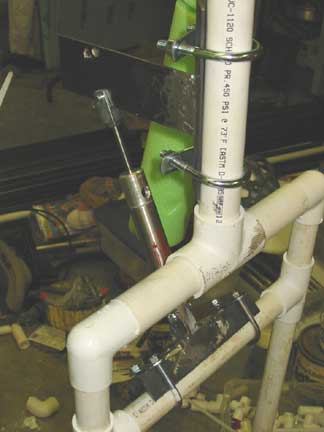 | ||||||||||||||||||||||
| Here's photos of the air cylinder assembly. The angle steel pieces are attached to the PVC with U-bolts. No drilling needed. Depending on the size of the cylinder you have handy, the upper bracket can slide up and down several inches to accommodate the cylinder. I had a small surplus air cylinder that I bought from C & H, but you can use whatever fits! (that's what I do!) Adjust the brackets and move the legs up and down to test the movement of the cylinder. Once you're satisfied with the movement, tighten down the brackets. The idea is to make the hips jump up a few inches, then jump back quickly. This will make the entire body flail about realistically (and disturbingly!) You can go ahead and connect up the air cylinder to the solenoid and test the action to be sure the frame works the way its intended. | | ||||||||||||||||||||||
| Note: When working with wire mesh, be sure to wear gloves! I attached a 34" piece of steel rod to the front of the upper bracket to make a waist and help define the upper body shape, but after I was done, I think the landscape cloth alone can serve to handle this... So its your option, rod or no rod! If no rod, be sure to zip tie the landscape cloth to the shoulders and to the front of the upper bracket. Cut a 2" hole in the center of the piece of landscape cloth, and fold it over the body (see the photo). use zip ties to attach the landscape cloth together at the sides and bottom. Bend and adjust the wire until it resembles a body shape. | |||||||||||||||||||||||
| Connect the air cylinder, solenoid and timer as shown. There are dozens of styles of solenoids, timers, and triggers - each combination affecting the details of connections. So without supplying specific parts which may be expensive or hard to obtain, its nearly impossible to describe details. I buy pneumatic parts from eBay, McMaster Carr, C & H, Surplus Center, junkyards, and my local hydraulic supply. When I start a project, I see what I have, and to some extent, build around the parts I've got! If you're not sure about air fittings, look in your yellow pages and find a local hydraulic supply. I've got a great relationship with a small supply shop. They are happy to answer my dumb questions and help me find the right combination of parts to hook up most anything I've brought in. I'm sure there's a supply near you that will be happy to help you sort out the details. What little I've learned about pneumatics has been by trial and error, and just trying to make it work. You can do it! Remember SAFETY when working with air... ALWAYS start testing with very, very low pressure - then work up to normal operating pressure. For a first attempt, start with 10 PSI, then work up in 10 PSI increments. Starting with low pressure lets you find and fix the air leaks and loose parts BEFORE slamming 60-100 PSI to the mechanics, potentially causing the mechanism to fly apart and harm to yourself or others.
|  | ||||||||||||||||||||||
| Pad the legs to give them some thickness and add realism. I had some packing bubble sheets lying around that I duct taped to the PVC leg pieces. Be sure to leave lots of room around the knees so the padding doesn't get caught in the knee joint. You may need to pad the buttocks area, too. Attach the pants using zip ties looped through the belt loops and through the landscape cloth. NOTE: do not attach the pants directly in the front. You'll need access to the inside to work on the moving parts. Its simple enough to open the front of the pants to get in. (no jokes, please!) Its hard to see, but the solenoid and fittings are held in the body with zip ties. The photo shows my test air connections. The finished body will use 3/8" black nylon tubing to supply air to the solenoid. | |||||||||||||||||||||||
| Fit the reducing coupling into the neck, and fit the 8" piece of 1/2 PVC to make the neck joint. Attach the Styrofoam wig head to the 1/2" pipe. Cover the head with whatever cloth you might have lying around (I had an old towel). I used a belt to wrap around the neck to hold the towel on. Attach hands (with zip ties, of course!). I screwed the heels of the shoes into the back of the 1/2" fittings on the foot. Then using zip ties, I tied the bottom of the pants leg to the tops of the shoes to keep the PVC hidden. The finished body is quite realistic in its movement. The body here has been flailing for as long as an hour continuously without a problem. I need to 'sprinkle' watered down paint to add some 'funkiness' to the clothes - after all, its been hanging out a long, long time! |


Subscribe to:
Posts (Atom)